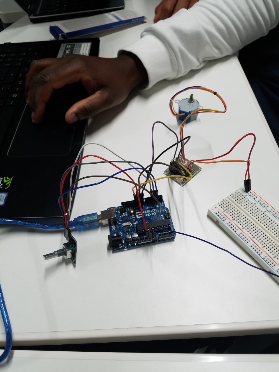
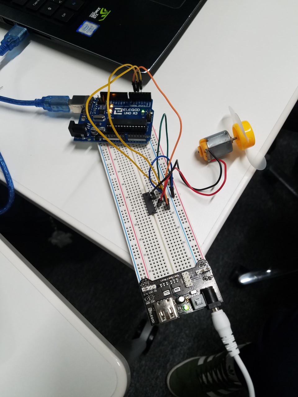
Final project – Automatic PET feeding System.

Component used:

  • Elegoo UNO R3
  • Ultrasonic Sensor
  • LCD 1602 Module
  • Breadboard
  • F-M wire
  • M-M wire
dav

https://pastebin.com/ps112Xqc

The aim of this project is to build a processor-based pet feeding system with Arduino. This system would be referred to as the “feeder”. The feeder is suitable for pet owners who leave their pets at home for long periods unattended. The objective is to feed a pet within regular intervals without the physical presence of the owner.

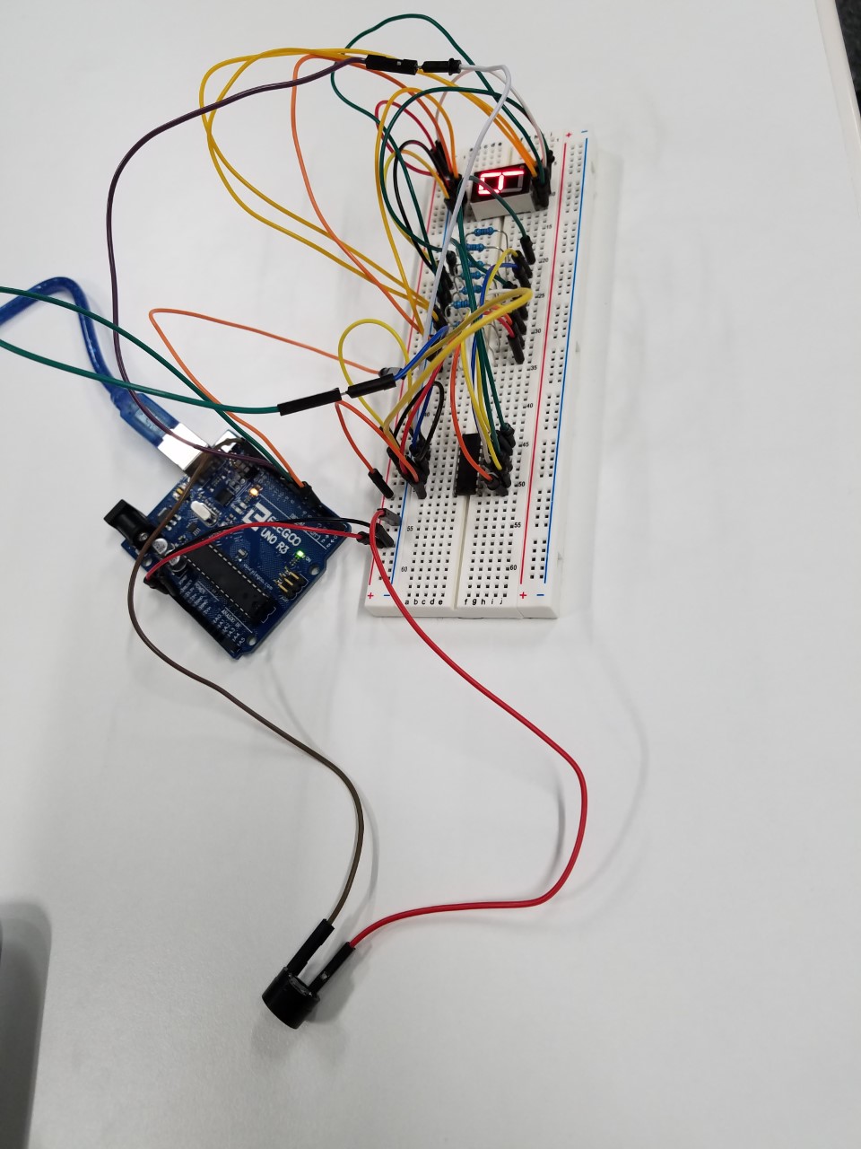
The features of the feeder includes a sensor which has has a proximity of 100cm. It is activated when the pet is in proximity and then automatically deactivated for a few hours to prevent multiple dispensation. This is a control feature and therefore regulates the number of times the pet feeds in a day.

An LCD screen is fitted to the breadboard and it displays a counter which records the number of times the pet was fed in a day. It is a meagre requirement however, it is useful to have statistics on the number of times the pet was fed. If the pet were to be avoid meals the entire day it could be an indication of illness or even death.

The time module (DS3232 RTC) is attached to the breadboard to implement the time and date. This is specifically for record purposes. It is a minuscule addition to the feeder system but it is helpful to know the days which had higher peak levels than others.

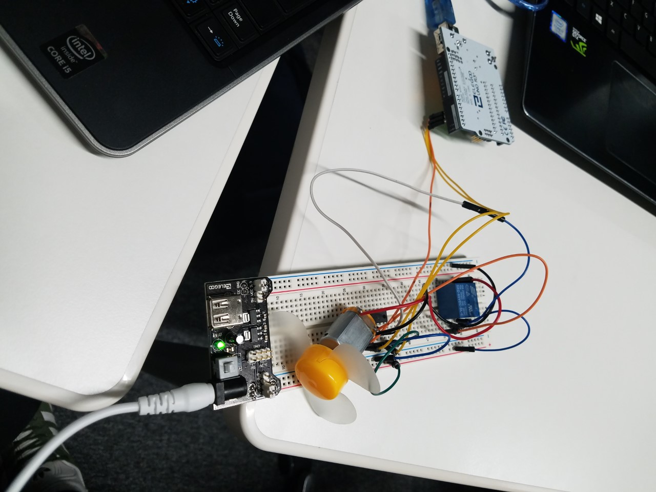
Finally, the servo motor is the most essential component of the Feeder system. It is critical to the success of the project. The main objective of the servo is to rotate at a 60 degree angle to open a tray that dispenses a measured quantity of food when the sensor in activated. As described earlier the sensor is deactivated after the initial dispense to avoid multiple dispensation. It is a very responsive motor and it is efficient in activating a dispense.

Lesson 33 Controlling Stepper Motor With RotaryEncoder

//www.elegoo.com
//2016.12.12

include “Stepper.h”

define STEPS 32 // Number of steps for one revolution of Internal shaft

                // 2048 steps for one revolution of External shaft

volatile boolean TurnDetected; // need volatile for Interrupts
volatile boolean rotationdirection; // CW or CCW rotation

const int PinCLK=2; // Generating interrupts using CLK signal
const int PinDT=3; // Reading DT signal
const int PinSW=4; // Reading Push Button switch

int RotaryPosition=0; // To store Stepper Motor Position

int PrevPosition; // Previous Rotary position Value to check accuracy
int StepsToTake; // How much to move Stepper

// Setup of proper sequencing for Motor Driver Pins
// In1, In2, In3, In4 in the sequence 1-3-2-4
Stepper small_stepper(STEPS, 8, 10, 9, 11);

// Interrupt routine runs if CLK goes from HIGH to LOW
void isr () {
delay(4); // delay for Debouncing
if (digitalRead(PinCLK))
rotationdirection= digitalRead(PinDT);
else
rotationdirection= !digitalRead(PinDT);
TurnDetected = true;
}

void setup () {

pinMode(PinCLK,INPUT);
pinMode(PinDT,INPUT);
pinMode(PinSW,INPUT);
digitalWrite(PinSW, HIGH); // Pull-Up resistor for switch
attachInterrupt (0,isr,FALLING); // interrupt 0 always connected to pin 2 on Arduino UNO
}

void loop () {
small_stepper.setSpeed(700); //Max seems to be 700
if (!(digitalRead(PinSW))) { // check if button is pressed
if (RotaryPosition == 0) { // check if button was already pressed
} else {
small_stepper.step(-(RotaryPosition*50));
RotaryPosition=0; // Reset position to ZERO
}
}

// Runs if rotation was detected
if (TurnDetected) {
PrevPosition = RotaryPosition; // Save previous position in variable
if (rotationdirection) {
RotaryPosition=RotaryPosition-1;} // decrase Position by 1
else {
RotaryPosition=RotaryPosition+1;} // increase Position by 1

TurnDetected = false;  // do NOT repeat IF loop until new rotation detected

// Which direction to move Stepper motor
if ((PrevPosition + 1) == RotaryPosition) { // Move motor CW
  StepsToTake=50; 
  small_stepper.step(StepsToTake);
}

if ((RotaryPosition + 1) == PrevPosition) { // Move motor CCW
  StepsToTake=-50;
  small_stepper.step(StepsToTake);
}

}
digitalWrite(8, LOW);
digitalWrite(9, LOW);
digitalWrite(10, LOW);
digitalWrite(11, LOW);
}

Lesson 32 Controlling Stepper Motor WithRemote

//www.elegoo.com
//2016.12.12

include “Stepper.h”

include “IRremote.h”

/—– Variables, Pins —–/

define STEPS 32 // Number of steps per revolution of Internal shaft

int Steps2Take; // 2048 = 1 Revolution
int receiver = 12; // Signal Pin of IR receiver to Arduino Digital Pin 6

/—–( Declare objects )—–/
// Setup of proper sequencing for Motor Driver Pins
// In1, In2, In3, In4 in the sequence 1-3-2-4

Stepper small_stepper(STEPS, 8, 10, 9, 11);
IRrecv irrecv(receiver); // create instance of ‘irrecv’
decode_results results; // create instance of ‘decode_results’

void setup()
{
irrecv.enableIRIn(); // Start the receiver
}

void loop()
{
if (irrecv.decode(&results)) // have we received an IR signal?

{
switch(results.value)

{

  case 0xFFA857: // VOL+ button pressed
                  small_stepper.setSpeed(500); //Max seems to be 500
                  Steps2Take  =  2048;  // Rotate CW
                  small_stepper.step(Steps2Take);
                  delay(2000); 
                  break;

  case 0xFF629D: // VOL- button pressed
                  small_stepper.setSpeed(500);
                  Steps2Take  =  -2048;  // Rotate CCW
                  small_stepper.step(Steps2Take);
                  delay(2000); 
                  break;

}

  irrecv.resume(); // receive the next value
             digitalWrite(8, LOW);
             digitalWrite(9, LOW);
             digitalWrite(10, LOW);
             digitalWrite(11, LOW);       

}

}/* –end main loop — */

Lesson 31 StepperMotor

//www.elegoo.com
//2016.12.12

/*
Stepper Motor Control – one revolution

This program drives a unipolar or bipolar stepper motor.
The motor is attached to digital pins 8 – 11 of the Arduino.

The motor should revolve one revolution in one direction, then
one revolution in the other direction.

*/

include

const int stepsPerRevolution = 1500; // change this to fit the number of steps per revolution

// initialize the stepper library on pins 8 through 11:
Stepper myStepper(stepsPerRevolution, 8, 10, 9, 11);

void setup() {
// set the speed at 20 rpm:
myStepper.setSpeed(20);
// initialize the serial port:
Serial.begin(9600);
}

void loop() {
// step one revolution in one direction:
Serial.println(“clockwise”);
myStepper.step(stepsPerRevolution);
delay(500);

// step one revolution in the other direction:
Serial.println(“counterclockwise”);
myStepper.step(-stepsPerRevolution);
delay(500);
}

Lesson 30Relay

//www.elegoo.com
//2016.12.12

/ Exercise the motor using the L293D chip /

define ENABLE 5

define DIRA 3

define DIRB 4

int i;

void setup() {
//—set pin direction
pinMode(ENABLE,OUTPUT);
pinMode(DIRA,OUTPUT);
pinMode(DIRB,OUTPUT);
Serial.begin(9600);
}

void loop() {

//—back and forth example
Serial.println(“One way, then reverse”);
digitalWrite(ENABLE,HIGH); // enable on
for (i=0;i<5;i++) {
digitalWrite(DIRA,HIGH); //one way
digitalWrite(DIRB,LOW);
delay(750);
digitalWrite(DIRA,LOW); //reverse
digitalWrite(DIRB,HIGH);
delay(750);
}
digitalWrite(ENABLE,LOW); // disable
delay(3000);
for (i=0;i<5;i++) {
digitalWrite(DIRA,HIGH); //one way
digitalWrite(DIRB,LOW);
delay(750);
digitalWrite(DIRA,LOW); //reverse
digitalWrite(DIRB,HIGH);
delay(750);
}
digitalWrite(ENABLE,LOW); // disable
delay(3000);
}

Lesson 29 DCMotors

int i;

void setup() {
//—set pin direction
pinMode(ENABLE,OUTPUT);
pinMode(DIRA,OUTPUT);
pinMode(DIRB,OUTPUT);
Serial.begin(9600);
}

void loop() {
//—back and forth example
Serial.println(“One way, then reverse”);
digitalWrite(ENABLE,HIGH); // enable on
for (i=0;i<5;i++) {
digitalWrite(DIRA,HIGH); //one way
digitalWrite(DIRB,LOW);
delay(500);
digitalWrite(DIRA,LOW); //reverse
digitalWrite(DIRB,HIGH);
delay(500);
}
digitalWrite(ENABLE,LOW); // disable
delay(2000);

Serial.println(“fast Slow example”);
//—fast/slow stop example
digitalWrite(ENABLE,HIGH); //enable on
digitalWrite(DIRA,HIGH); //one way
digitalWrite(DIRB,LOW);
delay(3000);
digitalWrite(ENABLE,LOW); //slow stop
delay(1000);
digitalWrite(ENABLE,HIGH); //enable on
digitalWrite(DIRA,LOW); //one way
digitalWrite(DIRB,HIGH);
delay(3000);
digitalWrite(DIRA,LOW); //fast stop
delay(2000);

Serial.println(“PWM full then slow”);
//—PWM example, full speed then slow
analogWrite(ENABLE,255); //enable on
digitalWrite(DIRA,HIGH); //one way
digitalWrite(DIRB,LOW);
delay(2000);
analogWrite(ENABLE,180); //half speed
delay(2000);
analogWrite(ENABLE,128); //half speed
delay(2000);
analogWrite(ENABLE,50); //half speed
delay(2000);
analogWrite(ENABLE,128); //half speed
delay(2000);
analogWrite(ENABLE,180); //half speed
delay(2000);
analogWrite(ENABLE,255); //half speed
delay(2000);
digitalWrite(ENABLE,LOW); //all done
delay(10000);
}

Lesson 28 Four Digital Seven SegmentDisplay

int latch=9; //74HC595 pin 9 STCP
int clock=10; //74HC595 pin 10 SHCP
int data=8; //74HC595 pin 8 DS

unsigned char table[]=
{0x3f,0x06,0x5b,0x4f,0x66,0x6d,0x7d,0x07,0x7f,0x6f,0x77,0x7c
,0x39,0x5e,0x79,0x71,0x00};

void setup() {
pinMode(latch,OUTPUT);
pinMode(clock,OUTPUT);
pinMode(data,OUTPUT);
}
void Display(unsigned char num)
{

digitalWrite(latch,LOW);
shiftOut(data,clock,MSBFIRST,table[num]);
digitalWrite(latch,HIGH);

}
void loop() {
Display(1);
delay(500);
Display(2);
delay(500);
Display(3);
delay(500);
Display(4);
delay(500);
Display(5);
delay(500);
Display(6);
delay(500);
Display(7);
delay(500);
Display(8);
delay(500);
Display(9);
delay(500);
Display(10);
delay(500);
Display(11);
delay(500);
Display(12);
delay(500);
Display(13);
delay(500);
Display(14);
delay(500);
Display(15);
delay(500);
}

Lesson 27 74HC595 And SegmentDisplay

byte seven_seg_digits[10] = { B11111100, // = 0
B01100000, // = 1
B11011010, // = 2
B11110010, // = 3
B01100110, // = 4
B10110110, // = 5
B10111110, // = 6
B11100000, // = 7
B11111110, // = 8
B11100110 // = 9
};

// connect to the ST_CP of 74HC595 (pin 3,latch pin)
int latchPin = 3;
// connect to the SH_CP of 74HC595 (pin 4, clock pin)
int clockPin = 4;
// connect to the DS of 74HC595 (pin 2)
int dataPin = 2;

void setup() {
// Set latchPin, clockPin, dataPin as output
pinMode(latchPin, OUTPUT);
pinMode(clockPin, OUTPUT);
pinMode(dataPin, OUTPUT);
}

// display a number on the digital segment display
void sevenSegWrite(byte digit) {
// set the latchPin to low potential, before sending data
digitalWrite(latchPin, LOW);

// the original data (bit pattern)
shiftOut(dataPin, clockPin, LSBFIRST, seven_seg_digits[digit]);

// set the latchPin to high potential, after sending data
digitalWrite(latchPin, HIGH);
}

void loop() {
// count from 9 to 0
for (byte digit = 10; digit > 0; –digit) {
delay(1000);
sevenSegWrite(digit – 1);
}

// suspend 4 seconds
delay(3000);
}

Lesson 26 Photocell

int lightPin = 0;
int latchPin = 11;
int clockPin = 9;
int dataPin = 12;

int leds = 0;

void setup()
{
pinMode(latchPin, OUTPUT);
pinMode(dataPin, OUTPUT);
pinMode(clockPin, OUTPUT);
}
void updateShiftRegister()
{
digitalWrite(latchPin, LOW);
shiftOut(dataPin, clockPin, LSBFIRST, leds);
digitalWrite(latchPin, HIGH);
}
void loop()
{
int reading = analogRead(lightPin);
int numLEDSLit = reading / 57; //1023 / 9 / 2
if (numLEDSLit > 8) numLEDSLit = 8;
leds = 0; // no LEDs lit to start
for (int i = 0; i < numLEDSLit; i++)
{
leds = leds + (1 << i); // sets the i’th bit
}
updateShiftRegister();
}

Assignment 25: The serial Monitor

Image

//www.elegoo.com
//2016.12.9
int latchPin = 11;
int clockPin = 9;
int dataPin = 12;
byte leds = 0;
void updateShiftRegister()
{
digitalWrite(latchPin, LOW);
shiftOut(dataPin, clockPin, LSBFIRST, leds);
digitalWrite(latchPin, HIGH);
}
void setup()
{
pinMode(latchPin, OUTPUT);
pinMode(dataPin, OUTPUT);
pinMode(clockPin, OUTPUT);
updateShiftRegister();
Serial.begin(9600);
while (! Serial); // Wait untilSerial is ready – Leonardo
Serial.println(“Enter LED Number 0 to 7 or ‘x’ to clear”);
}
void loop()
{
if (Serial.available())
{
char ch = Serial.read();
if (ch >= ‘0’ && ch <= ‘7’)
{
int led = ch – ‘0’;
bitSet(leds, led);
updateShiftRegister();
Serial.print(“Turned on LED “);
Serial.println(led);
}
if (ch == ‘x’)
{
leds = 0;
updateShiftRegister();
Serial.println(“Cleared”);
}
}
}