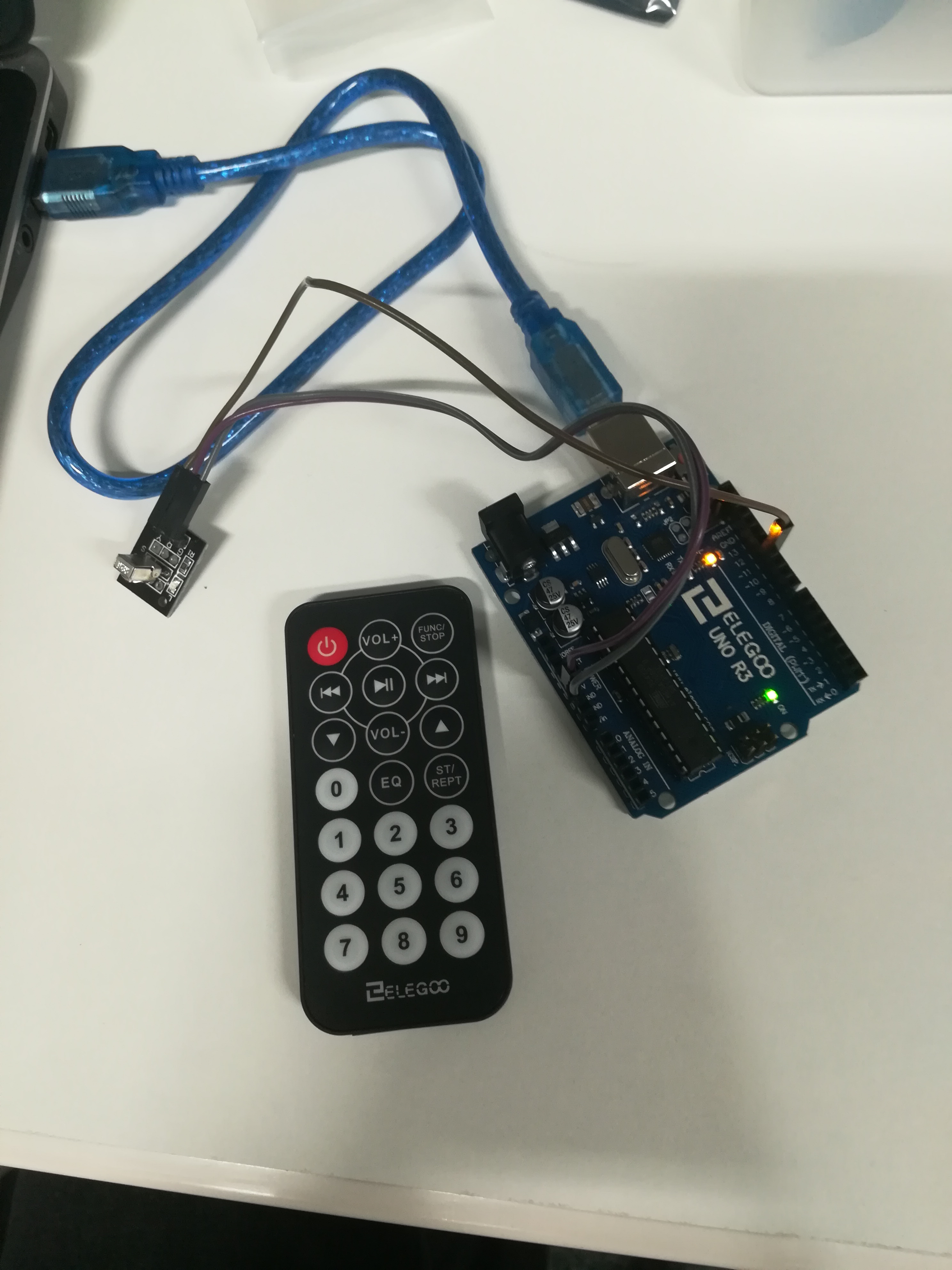
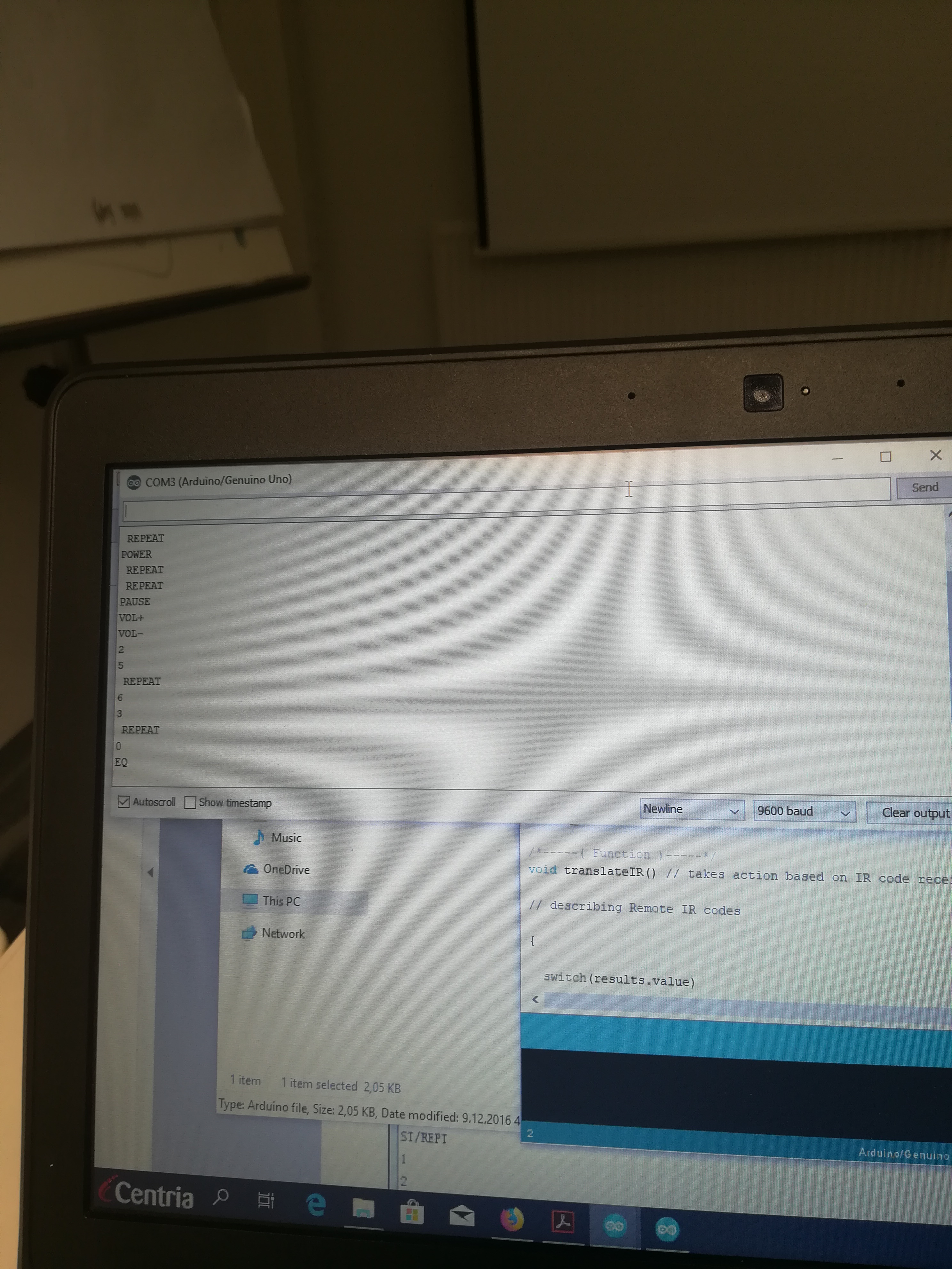
In this experiment we have connected the IR receiver to the UNO. The IR receiver is hardware which sends information from an infrared remote control to another device by receiving and decoding signals.
There are three different connection to the IR receiver sensor, Signal, voltage and Ground. below we can see the connection diagram and the coding.
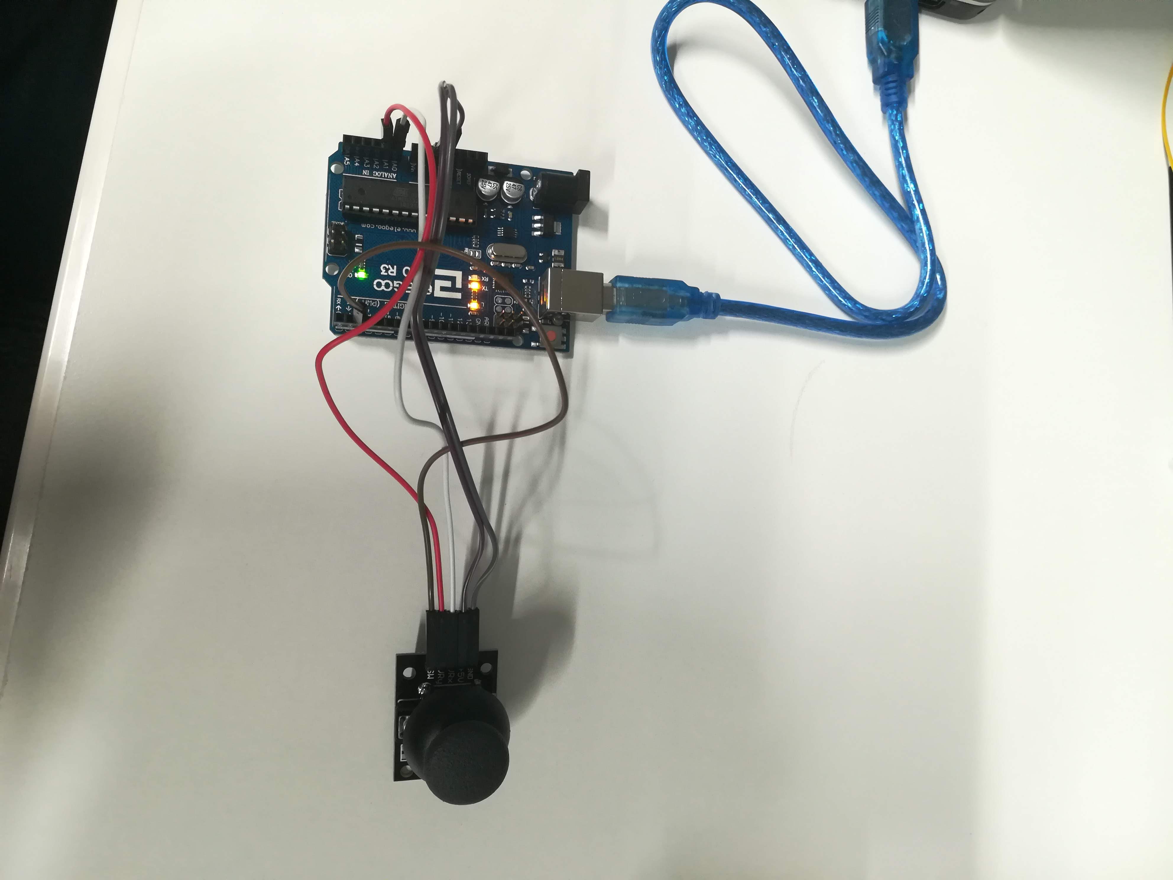
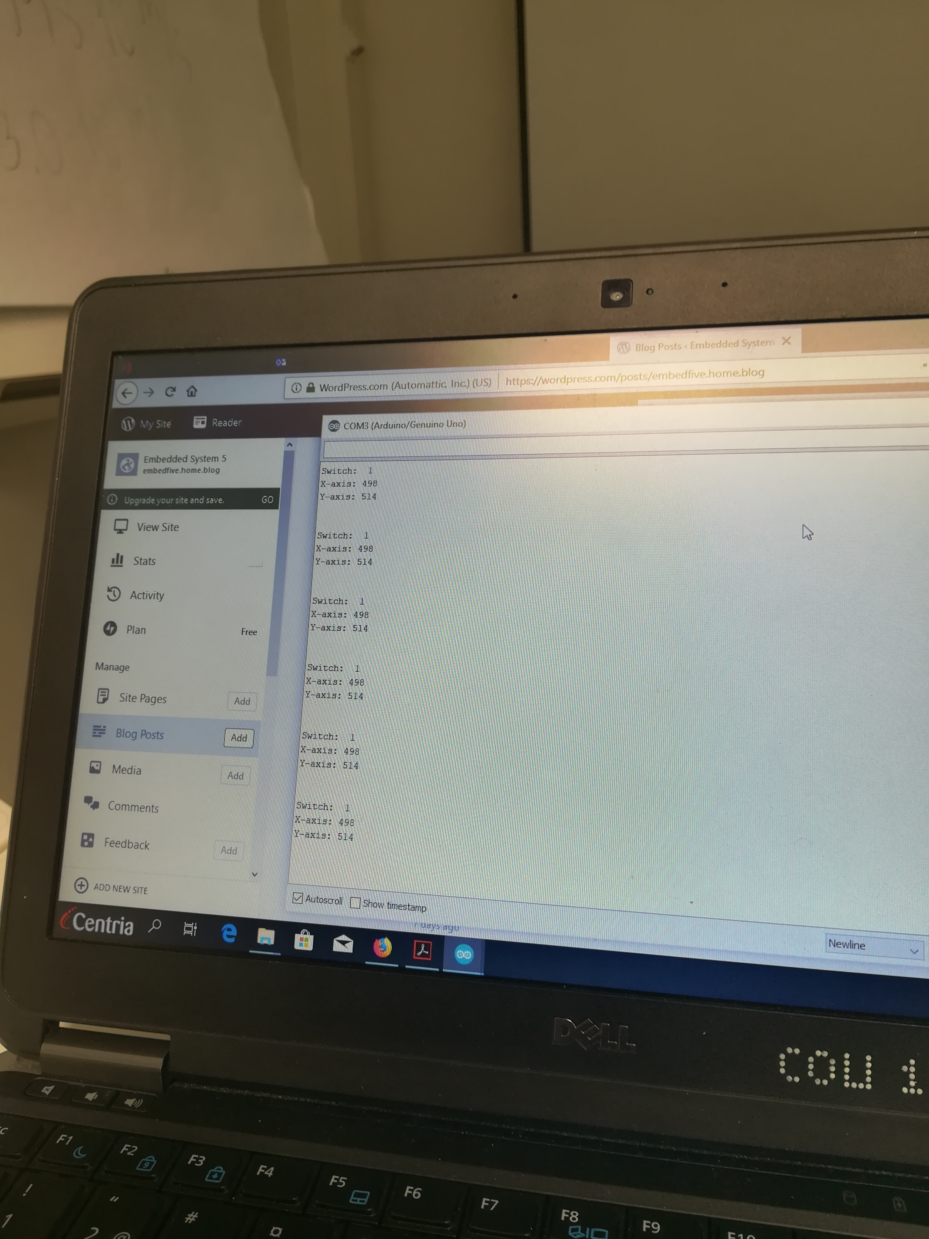
A joystick is known as an input device consisting of a stick that pivots on a base and reports its angle. it is also known as control column . analog joysticks helps a lot in controlling a project.
In this project we have learned how to use the analog joysticks module. The module of a joystick we have used has 5 pins which are VCC, Ground, X, Y keys. Here we have connected the joystick to the Elegoo UNO R3 through male to female wire.
Male to male jumper wire In In this project we are connecting a keypad to an UNO R3 board. we have connected the first pin of the keypad to D9, the second pin to D8, Third pin to D7, fourth pin to D6, fifth pin to D5, sixth pin to D4, seventh pin to D3, and the eighth pin to D2. below we can see the connection .
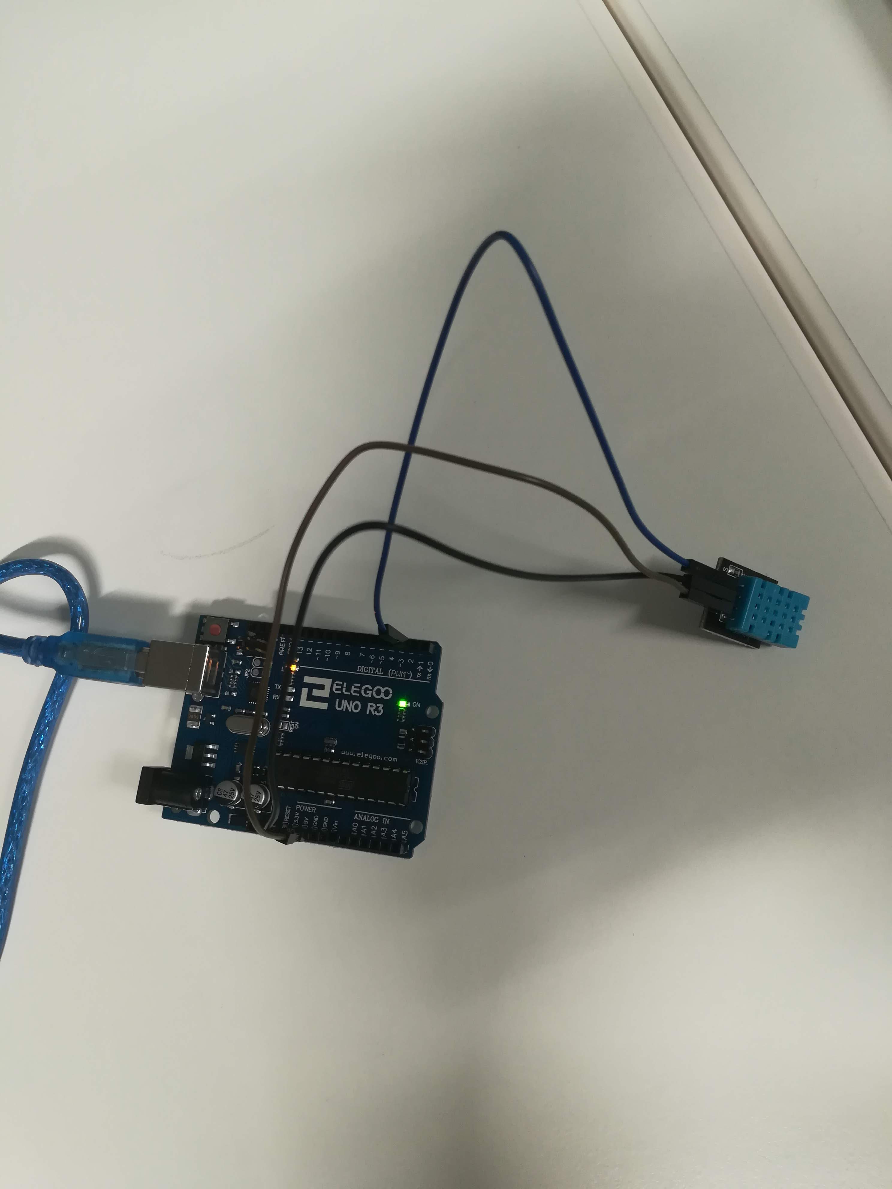
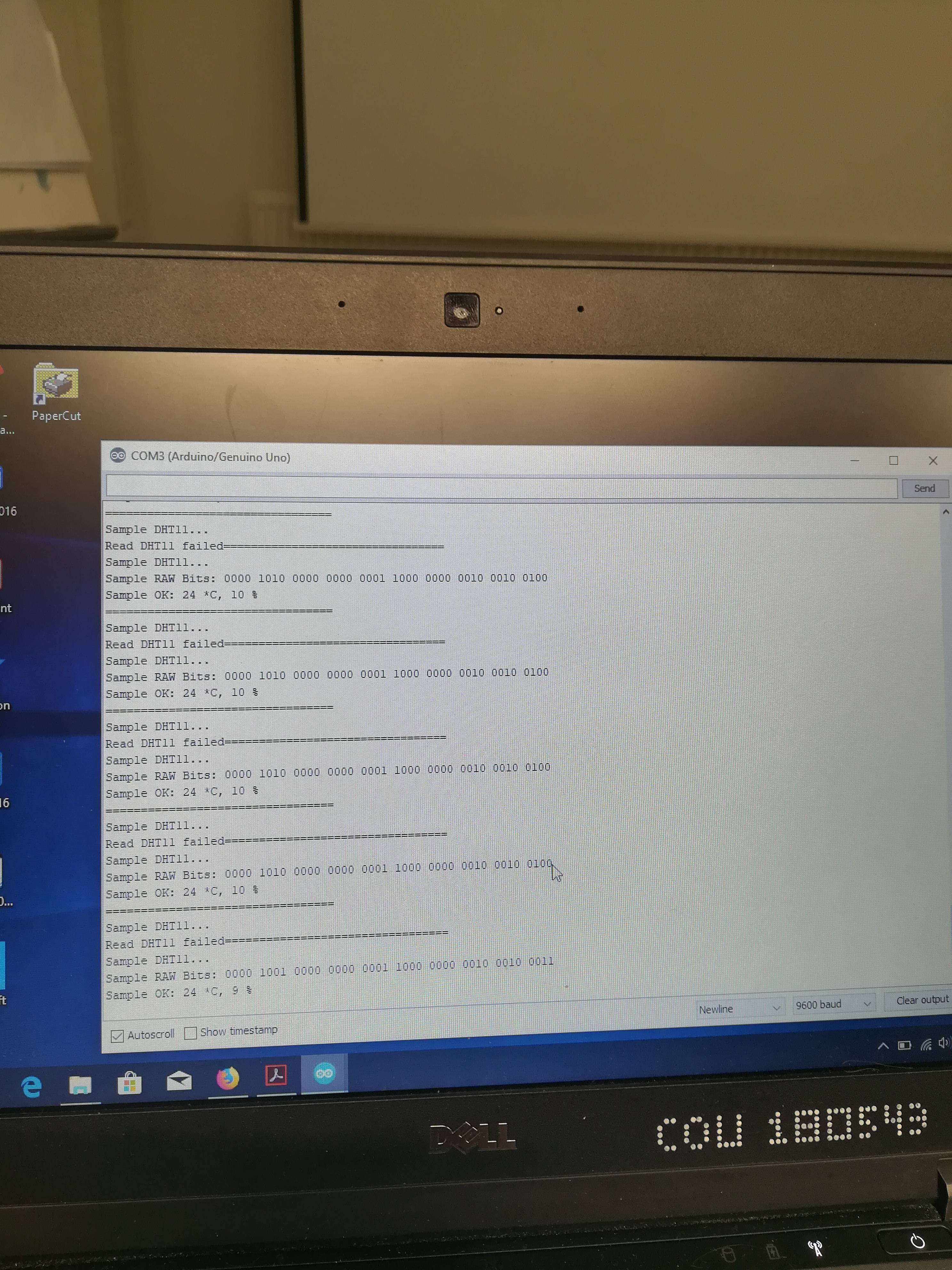
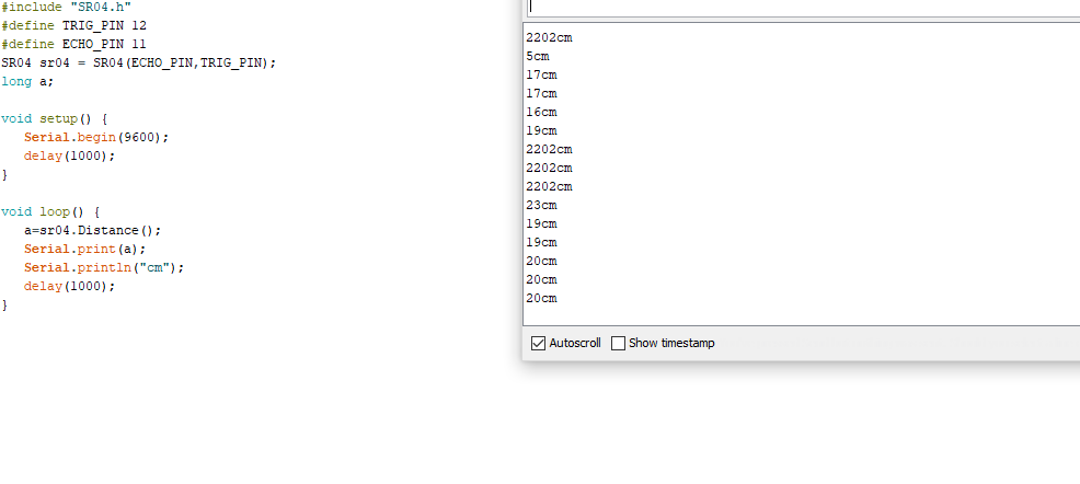
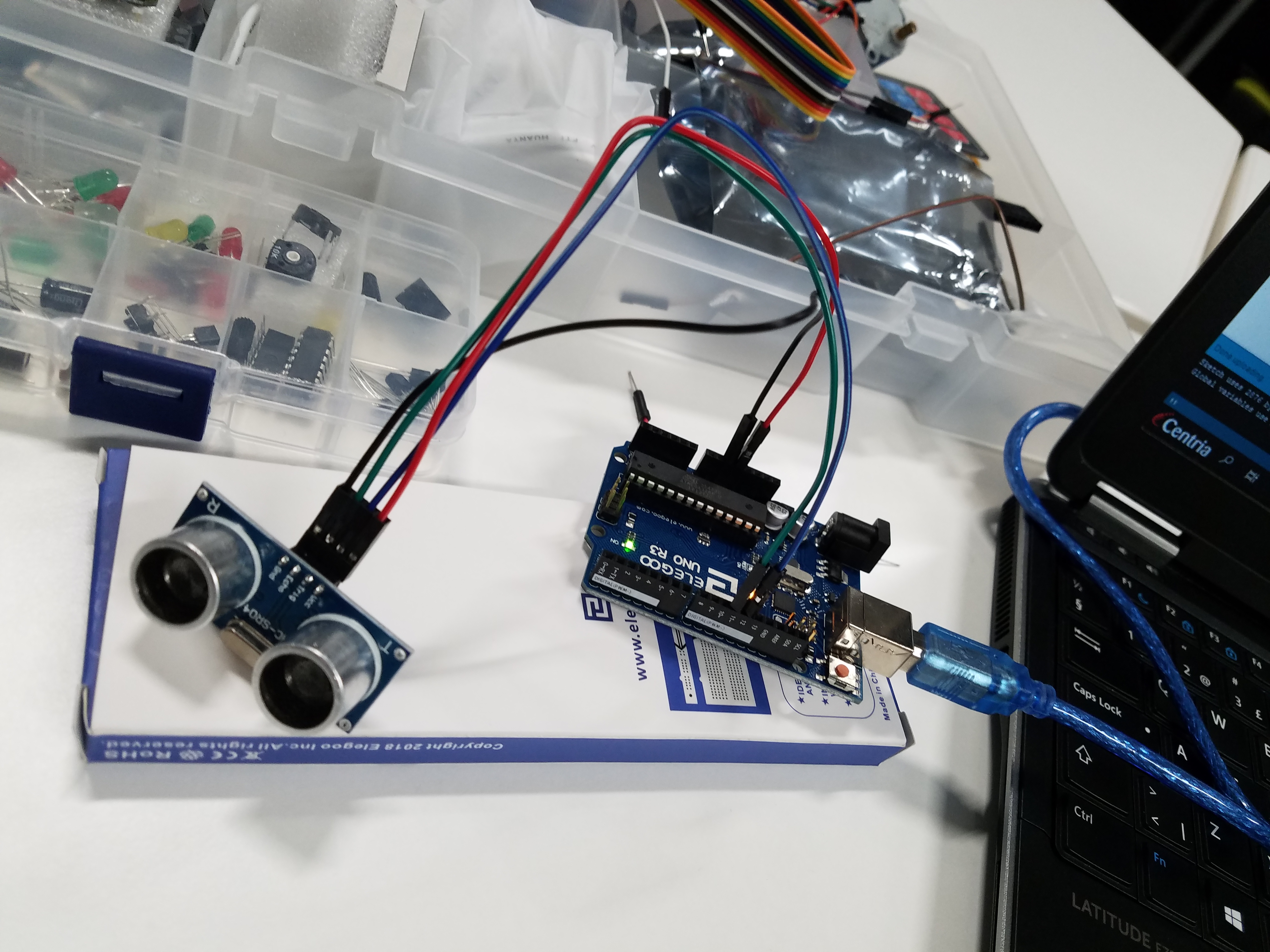
Component used: 1. Elego Uno R3 2. Ultrasonic sensor module 3. Female to Male Dupont wires
Ultrasonic sensor:
ultrasonic sensors measure distance by using ultrasonic waves. The sensor head emits an ultrasonic wave and receive the wave reflected back from the target.
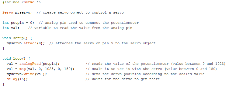
Component used: 1. Elego Uno R3 2. Servo (SG90) 3. Male to Male jumper wire
Servo motor:
A servo motor is a closed-loop system that uses position feedback to control its motion and final position. The main feature of the servo motors are the ability to precisely control the position of their shaft. Servo motors are used to control the position of objects, rotate objects, move legs, arms or hands of robots, move sensors etc. The best thing about a servo motor is that it can be connected directly to an Arduino.
Wiring Diagram: Here we have connected the yellow wire to the 5V pin Arduino, Servo brown wire to the Ground pin Arduino and Servo yellow wire to PWM (9) pin Arduino.
Code: When the program starts running, the servo motor will start rotate slowly from 0 degree to 180 degrees, one degree at a time. when the motor has rotated 180 degree , it will begin to rotate in the other direction until it returns to the home position.
1.Elegoo Uno R3 2.Tilt Ball Switch 3. Female to Male DuPont wires
In this experiment, we used tilt ball to detect high and low orientation. Tilt ball sensor is a component that can detect the tilting of an object. this type of sensor is the enviromental-friendly version of a mercury switch. Tilt balls are small, inexpensive, low power and easy-to-use.
In our experiment, we have connected the black wire to the ground and the white one is to number two through tilt ball switch.
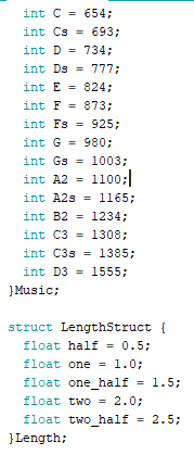
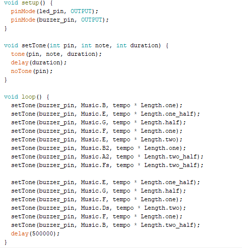
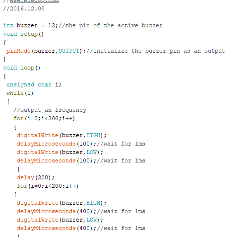
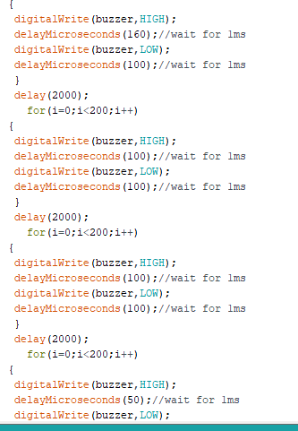
In this experiment, we used the passive buzzer to generate different sounds by changing different frequencies. The passive buzzer is like an electromagnetic speaker which requires an AC signal to produces the sound. Rather than producing a tone automatically, a changing input signal produces the sound. Firstly we connected the buzzer to the UNO R3 board, one wire connected to the pin 8 and the other one connected to the ground. We generated eight different sounds having different frequencies
In this experiment we learn to generate sound using a buzzer. The goal is to manipulate frequencies to produce a specific pitch. If the delay is increased the frequency is decreased accordingly. In order to understand the theory we decided to experiment using different delays which meant the periods varied. This produces different frequencies which might have a symphony if selected carefully. Musical notes can be easily composed by choosing specific delays. The buzzer can also be used to trigger an interrupt in alarm system.
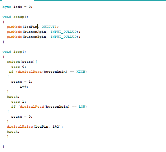
In this week’s assignment we test the use of digital inputs using two push buttons to turn an LED on or off. Pressing one button turns the LED on and pressing the other button turns it off. We connected the wires as shown in the diagram and added the code to activate the control of the LED. After successful testing we decided to make a few modifications by using a state diagram to control the LED using only one button. The code we used is displayed in the diagram below.