We examined the Led connection possibility and modifications associated with it.The breadboard is connected to the Arduino UNO R3 . The RGB LED is connected on the breadboard and three 200 ohms resistors were connected to the RGB pins respectively.The cathode pin was connected to the ground.Initially the LED did not light up because it had to be programmed to function using a code.
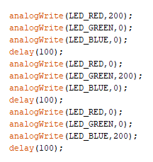
We included a simple code which detailed a loop consisting of the 5v powering up the R pin while the other pins are set to zero. It is then repeated for the G and B pins using the loop. This was successful we had a delay of 1000 to observe the changes slowly.
We then created a state machine in which the LED changed from Red to green using 5 RGB value increments.We also tested a state machine which changed the LED from Green to Blue.We also tried to use Analog Read() function to read the values of the potentiometer with the help of a serial.print. we also used the Analog Write() function to visualize the pulse width modulation.